Overview of Gas – Lift; Part 1: Gas Lift History, Fundamentals, Mandrels, Valves Types, and a Typical Field Installation
By
Frank E. Ashford, Ph.D.
Introduction: Gas - Lift History in the USA
Oil and Gas production has been an integral part of the World’s energy-based economy for over 160 years. In 1859, the Drake well in Titusville Pennsylvania ushered in the formidable sector of oil and gas production into the USA. It was soon discovered that oil and gas wells would flow naturally for a limited time until bottom hole pressure, and temperature conditions would not allow natural flow to the surface. In 1869 basic conventional Oil Well Pumping units were installed. Thus, what is termed in today’s Oil-Field terminology “Artificial Lift” was born.
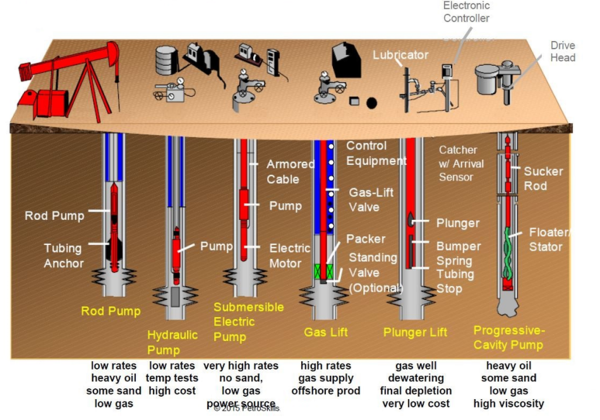
Artificial Lift systems have developed over the years, and in today’s Oil and Gas Industry there are six (6) commonly applied methods for artificial lift (AL). These applications are shown in Figure 1 [1]. As shown, applications vary from Rod Pumps, Hydraulic Pumps, Electrical Submersible Pumps (ESP), Gas Lift, Plunger Lift, and Progressive Cavity Pumps. The Figure indicates a brief statement regarding the specific application advantage of each AL system. The spring-loaded Gas Lift Valve was introduced during the1930’3, and many important improvements to the design were implemented after the 1940’6 Artificial Lift has been employed with a wide variation of results in the methods of application in the USA for almost 150 years. Figure 2 [2] shows the percentage application of each artificial lift process as employed in today’s oilfield environment.
The total producing well count in the USA is at an estimated number of 950,000 wells, which produce some 11 MMBPD of oil, and 96 BCF/D of gas, Artificial Lift is applied in approximately 50 % of these wells. Gas Lift installations account for some 10 % of all Artificial Lift applications, assuming Stripper Wells (less than 10 BPD) are included, or some 50,000 active Gas-Lift wells in the USA.
Figure 1. Six major ARTIFICIAL LIFT systems in application [1]
Figure 2. ARTIFICIAL LIFT systems in percentage of total application [2]
II) Gas Lift as an Important Artificial Lift Process
The basic principle for gas lift is primarily to inject a gaseous fluid (N2 and other inert gases have been applied) less in density than the flowing oil into the wells’ production tubing to “lighten” the weight of the oil/gas column and allow flow to the surface when oil flow is not possible due to the producing formation static pressure, IPR, and oil fluid and physical properties.
“Air-Lift” was first introduced in 1864 in Pennsylvania by Cockford applying compressed air in a pipe to lift oil form low producing rate, shallow wells. During the 1920s, completion systems with casing configurations, tubing, packers and standing valves were successful. However, Oil/Gas Production was sporadic as the operation of the standing valve was difficult to “couple” to the well’s productivity. The spring-operated gas lift valve (GLV) was invented in the 1930s, and enhanced field operations to allow for deeper wells and greater production rates. Improvements in new GLV designs were implemented after the 1940’s. In all GL applications, however, the pressure and volume of the injection gas was difficult to control due to the limited numerical models available to predict the Valves’ “CHOKE PERFORMANCE”. Perhaps the most applicable relationship was first introduced by Gilbert in his outstanding numerical review of flowing and gas-lift well performance in 1945 [3]. Several other formulas were developed, targeting specific reservoir Gas-Lift flow considerations. All of these “Gilbert-Type” choke formulas assume sonic flow (critical) conditions through a well head, or downhole choke; for this reason, they do not consider the differential pressure across the choke, where the sub sonic flow regime was leading to the “critical flow” for that installation. The other types of choke formulas considering both sonic and transition (sub sonic) were introduced by some pioneer researchers. Fortunati [4] in 1972 was the originator of this concept and his theory has been applied and validated. Fortunati was the first to mathematically identify sub sonic to sonic (critical) flow proving that the epsilon value: εcrit = Pup/Pdown (upstream to downstream critical pressure ratio) was not a singular value of 0.5 as had been observed and assumed by many field operations.
Ashford and Pierce [5] analyzed and correlated two phases upstream to downstream (vena - contract) production through downhole production tubing chokes in South Timbalier Bay, LA in 1973. Both critical, and subsonic regions were evaluated, showing variations in the ε (Pup/Pdown) value ranged approximately from 0.48-0.52, depending on both flowing pressures, as well as oil and gas physical and thermodynamic properties.
Field experience has proven that there are specific cases in which a well’s flow rate is changed by changing the downstream separator operation pressure. This condition, as shown by the cited authors, is a well in flow transition, i.e., “sub – sonic” flow in the downhole safety valve, as well as surface wellhead choke.
III) The Basic Gas Lift Well
As natural gas is a known hydrocarbon fluid with important physical property differences when compared to the density and viscosity of oil at any pressure and temperature. Its lesser density and viscosity make it a suitable addition to an oil flowing stream to “lighten” the transported fluid to the surface. Injection of gas is introduced through the tubing casing annulus. From the annulus, the gas enters the tubing through a mandrel containing the applicable GLV, or the standing GLV at the bottom of the tubing string. The mandrel is a single section of the production tubing string that allows insertion of the selected GLV. There may be more than one mandrel installed for a dead well “kick off” (well flow initiation). The final GLV is a single “orifice flow” type GLV and is packed off above the producing formation so the gas mixes readily with the existing oil to provide a lighter and more transmittable “flowing oil” with its corresponding GOR (Gas Oil Ratio), and injected gas to yield the flowing Gas Lift Ratio (GLR) allowing the well to produce oil/gas to the surface under its IPR (Inflow Performance Relationship) restrictions.
Essentially, the success of the process for a “deadwell” lies in the proper screening of a candidate well whose IPR will not allow any oil flow to the surface due to the lack of sufficient bottom-hole pressure. Another candidate well may be one with low GOR values, and a limited IPR.
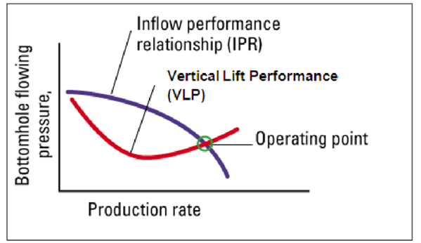
Figure 3 [6] illustrates the Inflow Performance Relationship over a range of flowrates and bottom hole pressures. The graph also shows the formation IPR, as well as the Vertical Lift Performance (VLP) relationship which is the bottom hole pressure required to force the produced fluids up the production tubing, and from the well head. It should be understood that the relationship between a well’s production capacity is related to the Reservoir “drawdown”, i.e. formation Pressure minus the Flowing Tubing Bottom Hole Pressure. This relationship, as indicated by Figure 3 [6] is dependent on many fluid and reservoir in-situ properties.
Figure 3. Relationship between a flowing wells’ Vertical Lift Performance (VLP) and the existing Formation (IPR) [6]
The flowing wells’ “VLP/IPR” relationships as related to the well’s flowing oil rate, GOR, and Casing Gas Injection (CGI) required for a Gas –Lift well to be in optimized conditions will be further discussed in Part II of this series.
The other Gas - Lift application option lies in properly selecting an existing “naturally flowing” well that may be operating far from its most “operationally optimal” conditions. Perhaps a higher Flowing Tubing Pressure (FTP) is required to transport the flow from this well to field gathering systems. Again, the free gas from the reservoir fluids GOR relationship may be at low levels, and this well may have been initially chosen as a “candidate” for future gas lift. Generally, these candidate wells may be completed with the standing GLV (essentially a choked flow device) above the production packer that seats the production tubing to the casing liner, allowing gas to enter the production tubing from this annulus.
As can be seen, the application of Gas Lift (GL) systems is primarily applied in these two field applications: 1) to change non-flowing - “dead wells” into a producing well, and 2) to increase production from low rate - “flowing wells” with a variation of the Flowing Tubing Pressure (FTP), and overall producing GLR.
Typical depth ranges in modern Gas Lift applications range from some 3000 to 8000 ft (915-2439 m). Generally, Gas Lift candidate wells have 28° – 35° API oil whose in-situ relative densities range from 0.89 - 0.84. Compared to the static gradient of water at 0.433 psi/ft (9.8 kPa/m), these indicate dead oil gradients of 0.39 - 0.36 psi/ft (8.8 – 8.1kPa/m).
Once gas has been injected into the well, it mixes with the produced oil and its solution GOR. The sum of the two amounts of gas, divided by the corresponding oil flow yields the Producing Gas Liquid Ratio, (GLR). The optimal flowing two-phase Gas Liquid Ratios (GLR’s) are generally set at some 1300 - 1600 MSCF/STB (231000 - 285000 std m3/STm3). This range allows establishing optimal producing well conditions with flowing gradients in the range of 0.13 to 0.18 psi/ft (2.9 - 4.1 kPa/m). There are four (4) basic Gas Lift Valves (GLV) in use, and these impact the proper selection for injecting casing gas into a preset mandrel to gasify the vertical liquid column in the tubing, thereby unloading the well, allowing for subsequent production.
III.A) The Gas Lift Mandrel – Gas Lift Valve (GLV) Configuration
As mentioned, the tubing string mandrel is a section of the producing tubing string that has a specific GLV installed. The depth, and gas flow capacity of each MANDREL/GLV are predetermined based of the formation oil gravity and GOR, as well as Gas Lift Injection Gas physical properties.
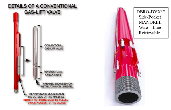
The following Figure 4 [7,8], indicates the basic differences between a Conventional, vs. a Side-Pocket wireline retrievable Gas-Lift mandrel. The conventional Gas Lift Valve (GLV) can be retrieved by pulling the tubing, whereas the wire-line retrievable valve is accessible with production tubing in place.
- Conventional (left) – require gas lift valves be installed in the mandrels on the surface and run with the tubing string.
- Side Pocket (right) – designed to permit gas lift valves and other downhole components to be installed or replaced with wireline without pulling the tubing.
Figure 4. Comparison of Conventional and Side –Pocket Gas Lift MANDRELS that are employed with Gas Lift Valves [7, 8]
A majority of gas-lift operations employ 2 3/8”- 2 7/8” production tubing and these have proven to be most adaptable to either style of mandrel. It is important to remember that the MANDREL is the device that holds the chosen GLV but is not a nodal element in the flowing oil as it traverses from formation to GLV injection point, and onwards to the tubing head and collection facilities on surface. Choice of conventional vs. wire-line retrievable mandrel depends on many factors:
- Depth of the flowing well: wire –line operations are complex at depths over some 8000 ft. (2439 m). The operations are not impossible by any means, but operators know that a producing well is not generally geometrically “vertical”, and some wire line issues may present themselves with a non-vertical completion. In these cases, the conventional mandrel is perhaps the better choice.
- Reservoir knowledge will play a big part in the selection of the mandrel. If the producing formation demonstrated favorable flowing conditions in gas lift wells, and a favorable IPR is present, the well is a good candidate for a conventional mandrel.
- If the well will be producing in a field where wax, sand, or other solid contaminants are present, the wire-line option deserves serious consideration.
- A wire-line mandrel features a side pocket profile to receive chemical injection valves, circulating valves, dummy valves, and dump kill valves.
- Several pocket porting configurations are available for applications such as water-flood injection, chamber lift, chemical injection, and annular flow.
Regardless of applying the Conventional vs. Wire-Line Mandrel, the next design/operational consideration relates to the operating GLV that will be introduced.
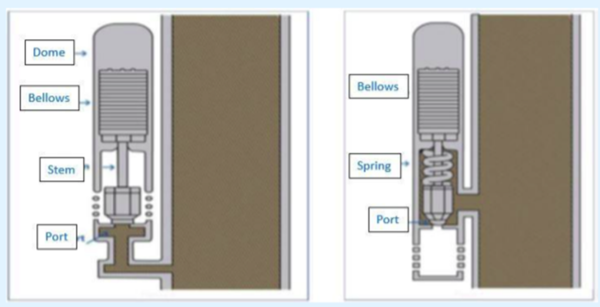
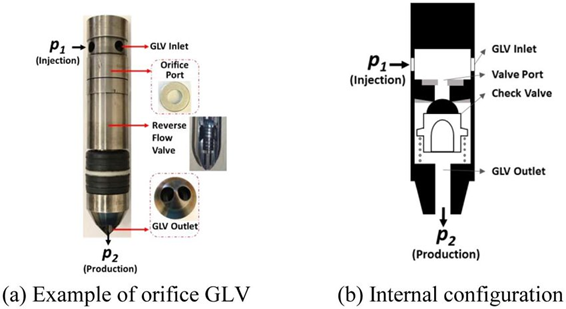
There are four (4) basic Gas-Lift Valve configurations: 1) CPO, (IPO) Casing/Injection pressure operated, 2) FPO, (TPO) Flowing/Tubing pressure operated, 3) TV, or Orifice Choke throttling valve, and 4) Combinations of the CPO/TPO class. Most gas lift operations employ the CPO valve due to its design adaptability and flowing pressure check valve installation. Generally, the lowest point of gas injection from the casing into the tubing is via an “Orifice Choke Valve”, Type 3) TV. This valve is sized to sustain the optimal casing gas injection volume, (CGI) that will unite with formation oil and its associated GOR. Figure 5 [7] shows the typical differences in the CPO, TPO valves, while Figure 6 [8] illustrates the internal of the Orifice Flow or TV type GLV.
Notice the in the CPO GLV design, the injection pressure operates against the valve dome pressure (usually N2) and controls the aperture pressure of the casing gas to be injected, which is initially set somewhat below the “dead liquid” head in the tubing. The casing gas injection pressure must be high enough in an operating “kick-off” valve to overcome the head of the higher density oil in the tubing. Once flow has been established, the flowing gradient of the two-phase fluid in the tubing string decreases, and the valve will close once the tubing pressure (and the corresponding casing pressure) is less than the dome set pressure.
Notice in the TPO valve design, the pressure port is now on the tubing side of the valve and its closing/opening process will be dictated by an increase/decrease of the flowing tubing pressure. In the TPO GLV operation, the “kick-off” is designed for the “dead oil” to open the valve upon completion. Injection Casing pressure must be greater than the tubing pressure so that injection gas flow is initiated. The induced two-phase oil, fluid GOR, CGI (casing gas injected), and resulting GLR produces a lower flowing tubing pressure at the mandrel due to the decreased flowing gradient, lowering the Flowing Tubing Pressure. The valve will close once the mandrel has performed its function at the designated depth.
Once all “unloading TPO/POC valves in the upper mandrels have performed their function to provide a multiphase flowing fluid for the reservoir, with an appropriate flowing gradient (psi/ft, kPa/m), gas injection here ceases. The well now responds solely to the Type 3, TV valve installed just above the tubing packer allowing only casing injection gas to be introduced.
Figure 5. Casing injection pressure (CPO) vs. flowing tubing pressure (TPO) operated GLVs. [7]
Figure 6. A Typical Orifice Flow “Choke” Gas Lift Valve as last GLV [13]
Figure 7. A Gas Lift valve showing its essential components [9]
Figure 7 [9] illustrates the various integrated components of a typical GLV. Inlet/Outlet gas ports, dome and bellows configuration, packings, and reverse flow check valve are shown. GLV’s rely on a restriction orifice (identified as the port in Figure 7) for control of injection gas flowrate. Correct design and configuration ensure that “critical” flow for a given orifice size is avoided. The casing gas injection rate and flowing conditions should, by design, yield subsonic flow through the selected Choke, or port. Further discussion on this topic will be addressed in Part II of this series on Gas Lift.
III.B) The Typical Gas-Lift Well Completion Module
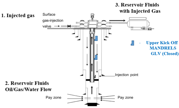
A properly designed and completed Gas Lift well possesses a specific Casing/Tubing/Liner/Packer design, with Gas Lift MANDRELS installed at predetermined depths in the production tubing. Figure 8 [10] indicates the bottom hole completion design for gas lift in a “dead-well” that is being brought into production. The Casing / Tubing / Liner, and Packer configuration displays the downhole to surface design that is characteristic.
Figure 8. Typical Flowing Gas –Lift well completion, showing the casing- production tubing-liner-packer configuration, with Kick –Off
MANDRELS, and last operating Orifice Choke GLV [10]
An existing flowing well may be chosen as a viable candidate for conversion into a Gas Lift Well in the future. For optimal production capacity, a single GLV, or Flowing Orifice (choke) valve is installed at time of completion at a predetermined distance above the Tubing / Liner / Packer to allow inflow from the oil producing zone. In the flowing well option, the kick-off mandrels may not have been installed as flow can be converted to gas lift while the well is in natural flow. Typical Gas Lift surface pressures are in operating ranges of some 500 – 2500 psi (3.4 – 17.2 MPa). Gas Lift installations usually include Unit Modules, comprising a Unit Group of 5 to 25 Wells that receive compressed gas from an associated Compressor Station, gas injection headers, and oil/gas production headers. Many comments have been cited relating to the production oil rate, Qo, and associated GOR/CIG/GLR “flowing gradients” (psi/ft, kPa/m) that are essential to proper Gas Lift performance. Additional Information regarding multiphase fluid flow will be addressed in Part II of this series.
III.C) Important Flowing Fluid Parameters in a Typical Gas-Lift Well
The solution Gas Oil Ratio, Rs, (GOR related in SCF/STB) is the gas that the reservoir oil has in solution in an oil reservoir at a specific pressure and temperature. This gas is liberated as the formation fluid is transported to the surface. The amount of flowing free gas will depend on the oil rate. It is important to note that the oil in production in the tubing string is not the actual Qo STB to be delivered at Standard Conditions (14.7 psia, 60 ºF; 101.3 kPa, 15 °C). The Oil Formation Volume Factor, Bo (bbl/STB), also plays an important role in the solution gas being liberated by flowing pressures and temperatures. Bo information is necessarily isothermal set at the producing formation temperature. Initial Boi values are seen to increase with decreasing pressure for well fluids above the Bubble Point Pressure, BPP, at the formation temperature. For these under-saturated reservoir fluids, initial Bo values are consequently greater than 1 due to formation fluid compressibility above the bubble Point (BPP), and generally range from 1.2 - 1.6 (approx.). As the saturation pressure, Ps, is reached, the Bos (saturated) is at its maximum, and gas is released as pressure decreases. The Bo decreases to a value of unity (1) at Standard Conditions where the oil is at Stock Tank conditions. At flowing pressures above the oil saturation pressure, no solution gas is produced in the tubing., At pressures below saturation pressure, Ps, Solution Gas flowing rates will be related to (Rsi – Rs), the initial Solution Gas, Rsi minus the existing Rs at flowing pressure in (SCF/STB, m3std/m3), or free gas flowing with the oil. The subsequent (Boi – Bo) values are directly related to the (Rsi- Rs) values. As the flowing pressure and temperature decrease in its traverse to the surface, the total Gas Lift Ratio (GLR) (SCF/STB, std m3/STm3) is the total of solution GOR vaporized, and the rate of injected casing gas CGI. The Oil Flow, and GLR are produced to the existing surface facilities. It is rather complex to obtain pertinent Bo, Rs values at various temperatures, so that, at best, the flowing oil/gas information is a valuable estimation. This approach has yielded good response both in design and operation for the Gas – Lift wells in the field.
III.D) A Typical Modular Installation Indicating the Location of Important Facilities to Accommodate the Gas-Lift Wells in the Field
It is clear that the total GOR is not released during the gas lift process. As pressures and temperatures vary, so will flowing amounts of flowing oil and gas conditions vary.
The application of both the Bo, and Rs fluid terms greatly aid in accurately estimating the final amounts of oil/gas flowing to the reception separator, and oil storage facilities. These are designed to handle the predicted flow of Oil, and GLR Gas. The sum of the two (2): Casing Injected Gas (CGI), and reservoir flowing gas, GOR, that are Bo, and Rs related, comprise the specific GLR for the candidate well. Each well in a module is a single player and must be directed to an integrated “Production Header”.
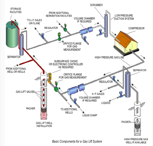
The produced oil and total gas are directed to production headers, field separators, storage facilities, and then to sales gas outlets. The remaining “Casing Injection Gas” is separated in the facility and directed to compression for providing the Gas Lift injection gas (IG) back to the Injection/Production wells. Figure 9 [11] summarizes in a modular display, the basic locations and functions related to the cited gas-lift gas injection, oil and gas production, separation of the produced stream to oil storage facilities, LP gas sales, and gas-lift gas metering and recompression.
Figure 9. The integrated Gas-Lift Modular Production Facility for a Single Well, Showing Gas Injection, Separation, Storage Facilities, LP Sales Gas, and Casing Injection Gas Recovery. [11]
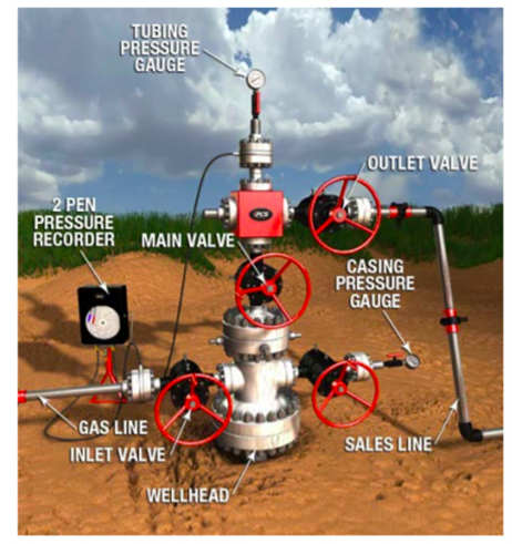
Figure 10 [12] is a simple field view of an operating Gas – Lift Well. As has been discussed regarding the well’s operation, its surface profile is quite straightforward in its installation and production. Shown are the:
- WELLHEAD
- MAIN VALVE
- INLET VALVE (Injection Gas)
- GAS LINE
- OUTLET VALVE (Oil/formation GOR/Casing Injected Gas (CIG))
- SALES LINE
- 2 PEN PRESSURE RECODER (Casing, and Tubing Monitoring)
- TUBING PRESSURE GAUGE
- CASING PRESSURE GAUGE
Figure 10. A typical Gas – Lift Well-Head Showing all pertinent connections [12]
Summary
In this Part 1 presentation of the initial Gas – Lift series, and effort has been made to provide for initial orientation regarding the important Gas – Lift history, initial background, initial production efforts, Gas – Lift components, and design criteria. The following summary encompasses this effort. Oil and Gas production has been an integral part of the World’s energy-based economy for over 160 years. Artificial Lift is applied in approximately 50 % of these wells. Gas Lift installations account for some 10 % of all Artificial Lift applications, assuming Stripper Wells (less than 10 BPD) are included, or some 50,000 active Gas – Lift wells in the USA.
Improvements in new GLV designs were implemented after the 1940’s. In all GL applications, however, the pressure and volume of the injection gas was difficult to control due to the limited numerical models available to predict the Valves’ “CHOKE PERFORMANCE”. Fortunati in 1972 [4] was the originator of this concept and his theory has been applied and validated
As natural gas possesses important physical properties differences when compared to the oil density, and viscosity at any pressure and temperature. Injection Gas is injected down the tubing casing annulus through a series of “kick – off” (well flow initiation) Mandrels containing the applicable GLV, or the standing GLV at the bottom of the tubing string. The Mandrel is a single section of the production tubing string with insertion of the selected GL. The depth, and gas flow capacity of each MANDREL/GLV are predetermined based of the formation IPR, oil gravity and GOR, as well as Gas Lift Injection Gas physical properties. A properly designed and completed Gas – Lift well possesses a specific Casing/Tubing/Liner/Packer design, with Gas Lift MANDRELS installed at predetermined depths in the production tubing for a “dead well”.
The solution Gas Oil Ratio, Rs, (GOR related in SCF/STB) is the gas that the reservoir oil has in solution in an oil reservoir at a specific pressure and temperature. This gas is liberated as the formation fluid is transported to the surface. The amount of flowing free gas will depend on the oil rate. The Oil Formation Volume Factor, Bo (Bbl/STB), also plays an important role in the solution gas being liberated by flowing pressures and temperatures.
To learn more about similar cases and how to minimize operational problems, we suggest attending our G4 (Gas Conditioning and Processing); ALS-Artificial Lift Systems; GLI- Gas-Lift; CAW - Well Completion and Workovers courses.
Acknowledgment:
The Author would like to recognize the expert, and valuable input to this document by Mr. Wes Wright, senior Instructor with PetroSkills/JMC. His explicit knowledge of the subject matter, and clarity of expression regarding all aspects of the Gas – Lift system were integral to this presentation.
References:
1. Hullio, et.al; Design and Economic Evaluation of the ESP and Gas Lift on the Dead Oil Well. Int. Journal of Current Engineering and Technology. Nov. 2018
2. Clegg, et.al; Relative Frequency of Different types of Artificial Lift Methods: 1993.
3. Gilbert, W.E. (Flowing and gas-lift well performance. API Drilling Production Practice 20:126–157, 1945)
4. Fortunati, F; Two-Phase Flow through Wellhead Chokes. Paper SPE 3742, 1972
5. Ashford, Pierce, The Determination of Multiphase Pressure Drops and Flow Capacities in Downhole Safety Valves, JPT, September, 1974
6. Gas Lift Optimization System – Symantic Scholar (Economides 1994)
7. Elldaki, Fathi Gas Lift System; Petroleum and Petrochemical Engr Journal Aug. 4 , 2017
8. SBRO-DVXTM - Side Pocket Gss-Lift Mandrel, 2021
9. K.L. Decker, SPE, Decker Technology. The paper has been peer reviewed and published in the February 2018 SPE Production & Operations journal
10. MEHDI ABBASZADEH SHAHRI, M.S. PhD Texas Tech – 2011
11. Parveen Industries Pvt Ldt. – Gas Lift Equipment
12. PCS Ferguson Opti-Flow® Gas Lift System Gas Lift Troubleshooting Guide
13. ReasearchGATE TM, 2021

