Our Blog

undefined

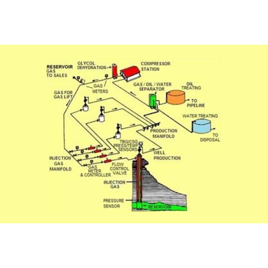
Part 3 of the Overview of Gas Lift series has procedures for identifying, selecting, and optimizing technical as well as field operations for a gas lift well. Section IIIA reviews the gas lift well candidate related to gas content in the reservoir fluid and a choice of gas lift or pumping. Section IIIB discusses the well completion related to dimensional and clearance considerations and gas lift facility requirements. Section IIIC has guides for kicking off a well and avoiding erosion cutting of the unloading valves. Section IIID provides the procedure to optimize the well once it has kicked off and is operating in the production system.

undefined

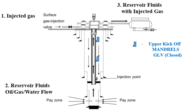
In the Part 1 of this Series on Gas Lift History and Basic Well Parameters, an attempt was made to bring into focus the primary “state of affairs” of Gas Lift operations in the USA. Part 2 will discuss basic Gas Lift well casing and tubing components, and their operational function, as well as Choke Flow relationships in Gas Lift wells. In the First Section II.A, Energy and Mass Balance relationships will be used to compute flowing pressure gradients, (dP/dL) (psi/ft) for injected casing gas ((dP/dL)g), and for further documents addressing this subject, multiphase flow in the tubing ((dP/dL)mp). Section II.B will address gas injected at surface into the annular space between production casing and tubing. The injection gas travels down the annular space on its way to either a “kickoff “gas-lift” valve located in a tubing MANDREL with an Injection Pressure Operated gas lift valve (IPO), or to the bottom Orifice GLV. Calculations will be performed to determine injected gas annular flow vs. pressure loss related to the 9 5/8” casing and either the 2 3/8”, or 2 7/8” production tubing. The flow is then considered in the annular space between the 7” liner and either the 2 3/8’’, or 2 7/8’’ production tubing. Casing gas flow does not encounter the 5” liner. Physical dimensions for these selections will be addressed. Section II.C presents the basic, single phase gas flow performance characterization related to CHOKE FLOW in the Gas Lift Valve. Once a valve has been fitted with a choke (orifice) size, the flow performance of a choke will follow the mass, and energy balance relationships related to isentropic gas expansion. This flowing condition for the choke MUST be selected in its transitional, sub-critical flow region so that additional changes to injection gas flowrates may be made if called for. It is essential to design the final Orifice GLV so that operation near, or in the Critical Regime (Sonic Flow) is avoided. A numerical example will be presented to illustrate the direct application Casing / Liner Gas injection data with the corresponding IPR Tubing Gas Lift Valve with installed CHOKE dimensions.

undefined

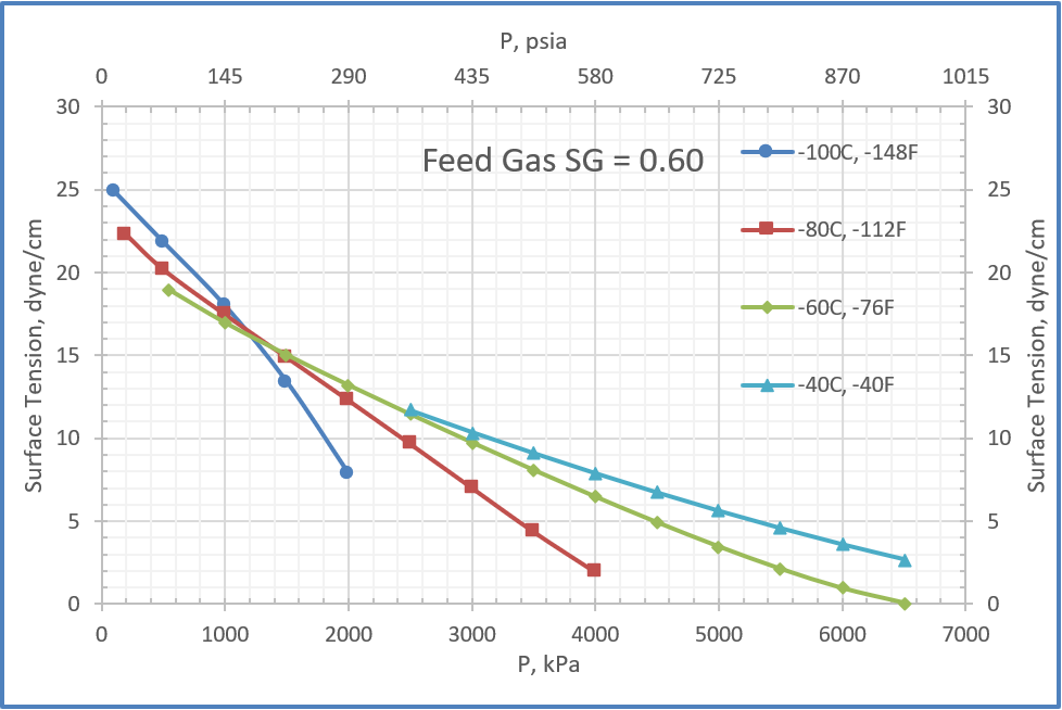
In December 2021 tip of the month (TOTM), we presented two simple empirical correlations for estimating pure liquids surface tensions of the paraffins methane through n-octane. The two correlations express the surface tension as a function of the reduced temperature and molecular weight with only two (first correlation) and four (second correlation) fitted parameters. These correlations and the smoothed experimental data were used to generate three figures for methane through n-octane and a few heavy ends with known molecular weights. In this follow-up TOTM, an estimation method for surface tension for the paraffin liquid mixtures in equilibrium with natural gas with a fixed feed composition will be presented. Using the SRK-EOS of ProMax five charts were generated to estimate the hydrocarbon liquid mixtures surface tensions, σ, as a function of temperature and pressure at a specified inlet feed gas relative density in the range of 0.6 to 0.8. The feed gas composition was flashed to varying temperatures and pressures within the two-phase region of the feed gas envelope to generate the liquid and vapor phases. The resulting liquid surface tension estimates were then plotted. In addition, the accuracy of a semi empirical approach based on the Macleod basic relationship to estimate σ was evaluated and summarized against the surface tension values calculated by ProMax.

undefined

Two simple empirical correlations and a corresponding states method reported in the literature are used to estimate pure liquids surface tensions for the paraffins methane through n-octane. The two correlations express the surface tension as a function of the reduced temperature and molecular weight with only two (first correlation) and four (second correlation) fitted parameters. These correlations and the smoothed experimental data were used to generate three figures for methane through n-octane and a few heavy ends with known molecular weights. The fitted parameters for these figures will be presented. To evaluate the accuracy of the two correlations, the corresponding states method by Zuo and Stenby was used to estimate the liquid n-heptane surface tension at several temperatures. The estimated surface tension values were compared with the results by the two correlations against the experimental values. The summary of error analysis indicates that the accuracy of the generated figures and the two correlations are good and can be used for facilities calculations. Because of the simplicities and ease of calculations, the two correlations are suitable for hand calculations. While the calculations by Zuo and Stenby method can be done by hand, it is more convenient with spreadsheets. In a follow-up tip, the methods for estimation of surface tension for the paraffin liquid mixtures will be presented.

undefined

In this Part 1 presentation of the initial Gas – Lift series, and effort has been made to provide for initial orientation regarding the important Gas – Lift history, initial background, initial production efforts, Gas – Lift components, and design criteria. Oil and Gas production has been an integral part of the World’s energy based economy for over 160 years. Improvements in new GLV designs were implemented after the 1940’s. In all GL applications, however, the pressure and volume of the injection gas was difficult to control due to the limited numerical models available to predict the Valves’ “CHOKE PERFORMANCE”. Injection Gas is injected down the tubing casing annulus through a series of “kick – off” (well flow initiation) Mandrels containing the applicable GLV, or the standing GLV at the bottom of the tubing string. The Mandrel is a single section of the production tubing string that allows insertion of the selected GLV. The solution Gas Oil Ratio, Rs, (GOR related in SCF/STB) is the gas that the reservoir oil has in solution in an oil reservoir at a specific pressure and temperature. This gas is liberated as the formation fluid is transported to the surface. The amount of flowing free gas will depend on the oil rate. The Oil Formation Volume Factor, Bo (Bbl/STB), also plays an important role in the solution gas being liberated by flowing pressures and temperatures.

undefined

This Tip of the Month will discuss energy issues in the U.S, and highlight why there must be an “all of the above” approach to electricity generation technologies to ensure availability and reliability. The type of technology selected should be based upon what the local resources and environment can provide as there is no silver bullet, or one size fits all solution. Energy density of the various electricity generation technologies will be covered, and some examples of current performance will be examined.